My Basket

Free Delivery - Mainland UK
Online orders over £300

Next day UK Delivery
On orders before 5pm

Knowledge Base


Find manuals, firmware &

setup guides

Search for answers to your questions by entering keywords below, or look through our knowledge base. 

Dahua

USER Guide and Videos

Error Codes

Alarm Wiring

Alarm connection block

Alarm connection block diagram

Output connection:

Output connection diagram

Example wiring

Example wiring diagram

Input Connection:

Input connection diagram

PTZ Keyboard

PC - Smart PSS Lite

Mobile Phone app

DMSS Alerts

Dahua Intercom

Single Villa Intercom

Download Guide Single Villa Intercom wiring diagram

Villa Multiple Intercom

Download Guide Villa Multiple Intercom wiring diagram

Apartment Intercom Setup

Download Guide Apartment Intercom Setup wiring diagram

Multiple Intercom Setup

Introduction

This guide is to assist with the initial set-up steps for a Dahua intercom setup using multiple VTO's and/or multiple VTH's in Villa Mode where all VTH's will ring together, it will include initialisation, configuration, troubleshooting and app integration steps. This guide will build upon QRG1103-01.

Network Map

Please connect the VTO and VTH to the POE switch, making sure your cable runs are 80m or less. You will also need a windows laptop, with the Dahua ConfigTool version 5 installed, on this network for initial configuration.

Connection Notes: If you wish to use a mobile App for notifications you will require to download the DMSS App from either App Store or Play Store. You will also require connection to a router for this to function.
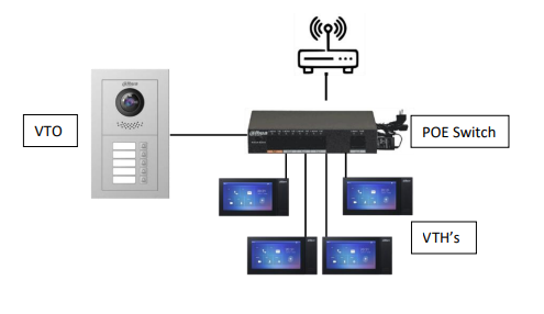
Multiple Intercom network map diagram

Initialisation

Using the windows laptop, search the network for devices using the ConfigTool, you will see two uninitialised devices in the search results.

Select the VTO and click Initialise, this will then prompt you for a device password, choose a password with a minimum of eight characters and a mixture of letters and numbers.

Once initialised, select the language of your choice.

Then select the VTH's and click Initialise, this will prompt you for a six-digit passcode.

Once initialised, again a prompt will appear to select the language of your choice.

Please make a note of these passwords.

Make sure that all devices are in the same IP range and in the same range as the router if used.

i.e., If your router is at 192.168.1.1, you will want to statically assign your devices as 192.168.1.XXX

Building Management

On the ConfigTool, go to building management and select Global Parameters.

From here, set Server type as VTO, set VTO password as the chosen password for the VTO's and set VTH password as the chosen passcode for the VTH's and click OK.

Set the Server Address as the VTO's IP address and all other sections of the global parameters can be left to default settings.

Click Add Node and this will then ask you about the building's configuration and layout.

De-select the check boxes for Building, Unit and Floor as shown below.

Select Unit VTO (Main) and Unit VTO (Sub) if second VTO is used.

Then enter the number of VTH's in use into extension number.

Building management Add Node configuration screen

This will give you one room with any number of extensions and one or more VTO's that can now be associated with the devices set up in the previous step, select one VTO at a time from the left list and the VTO's from the building plan and click Association, choosing one of the VTOs to be the main and one to be the sub, then doing the same for the VTH's.

Once all devices have been associated to the building management plan, click Association List, select all devices then click Config to push the settings out to the devices.

Adjustments and Troubleshooting

Once the building config has been pushed out to the devices, there are a few things to check, but the intercom should now be working.

First thing to check is the VTH's network settings, this is done by going to Device Config, double clicking each VTH and entering its passcode.

You will want to make sure that the SIP Server IP is set to the IP address of the main VTO, the SIP realm is VDP and the Login Password is set to the VTO's password.

Next go to Network Terminals and check that the Main VTO IP is set to the VTOs IP address and the Main VTO Pwd is set to the VTO's password. Repeat these steps for each VTH being used.

If used, login to the Sub VTO's webpage, go to Network and check that the SIP server address is set to the main VTO's IP address then navigate to the IP address of the main VTO and login.

Go to local settings, make sure that the group call button is enabled, then go to network settings, and make sure that the SIP server is enabled. Changing either of these settings will reboot the main VTO.

Go to Household Management and then status and check to make sure that all the VTO's and VTH's are listed as Online.

The Intercom is now ready to be tested, if the VTH's ring when the VTO button are pushed, the setup is configured correctly, if not, default the devices (using the Factory Default button in System Settings of the ConfigTool) and start again.

DMSS Integration

Log into VTO IP address then go to Network and ensure cloud is online.

On the DMSS app, go to Add device and scan the QR code from VTO network page. Select VTO and enter its login details. Now press the button on the main VTO, which should alert the mobile phone. Check the sub VTO does the same if used.

Dahua Apartment Intercom Setup

Introduction

This guide is to assist with the initial set-up steps for a Dahua intercom system when needing to have multiple independent rooms that are individually addressed, such as an apartment building or office complex.

This guide will include initialisation, configuration, troubleshooting and app integration steps.

Modules

The VTO4202F range is a modular system, this means that the modules will need to be connected in series using the included ribbon cables, it is recommended to do this before initialisation, making sure that each ribbon cable is securely seated and are fitted correctly following the In and Out markings on each of the modules.

Network Map

Please connect the VTO and all VTH's to a POE switch, making sure your cable runs are 80m or less. You will also need a windows laptop, with the Dahua ConfigTool version 5 installed, on this network for initial configuration.

Connection Notes: If you wish to use a mobile App for notifications you will require to download the DMSS App from either App Store or Play Store. You will also require connection to a router for this to function.
Apartment Intercom network map diagram

Initialisation

Using a windows laptop and the Dahua ConfigTool, search the network for devices, you will see your uninitialised devices in the search results.

Select the VTO and click Initialise, this will then prompt you for a device password, choose a password with a minimum of eight characters and a mixture of letters and numbers.

Once initialised, a prompt will appear to select the language of your choice.

Then select the VTH's and click Initialise, this will prompt you for a six-digit passcode.

Once initialised, again a prompt will appear to select the language of your choice.

Please make a note of these passwords

You will need to make sure that all devices are in the same IP range and in the same range as the router if used.

i.e., If your router is at 192.168.1.1, you will want to statically assign your devices as 192.168.1.XXX

For the apartment setup, it is recommended to use the ConfigTool Export button to create a reference document in Excel that will keep track of room numbers, IP addresses, Mac addresses and passwords of each device in the system.

Building Management

On the ConfigTool, go to building management and select Global Parameters.

From here, set Server type as VTO, set VTO password as the chosen password for the VTO and set VTH password as the chosen passcode for the VTH's and click OK.

Se the Server Address to the VTO's IP address and all other sections of the global parameters can be left to default settings.

Click Add Node and this will then ask you about the building's configuration and layout, for this setup you will want to select Unit VTO (Main) and de-select the check boxes for Building, Unit and Floor as shown below.
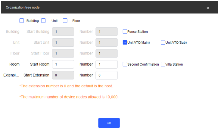
Building management Add Node configuration screen

You then need to enter the number of VTH's into Room Number. This will give you a plan with the chosen number of rooms and one VTO.

Associate devices by selecting the VTO from the left list and the VTO from the building plan and clicking Association.

For the VTH's it is worth checking the Excel sheet created during initialisation so that the correct VTH's are associated to the correct room numbers, matching serial numbers to their room numbers.

Once all devices have been associated to the building plan, click Association List, select all devices then click config to push the settings out to the devices.

Then navigate to the webpage of the VTO, click Local and choose which modules you have fitted by adding them to visual layout.

If you have push button modules, clicking the blank rectangle will let you link that button to one of the assigned rooms.

Adjustments and Troubleshooting

Once the building config has been pushed out to the devices and the modular layout selected, there are a few things to check, but the intercom should now be working.

First thing to check is the VTH network settings, this is done by going to Device Config, double clicking the VTH and entering its passcode.

You will want to make sure that the SIP Server IP is set to the IP address of the VTO, the SIP realm is VDP and the Login Password is set to the VTO's password.

Next go to Network Terminals and check that the Main VTO IP is set to the VTOs IP address and the Main VTO Pwd is set to the VTO's password.

Then navigate to the IP address of the VTO and login.

Go to household management and then status and check to make sure that the VTO and all VTH's are listed as Online.

The Intercom is now ready to be tested, if each VTH rings when the VTO calls it, the setup is configured correctly, if not, default the devices and start again.

DMSS Integration

Go to network on the VTO's webpage and check that cloud service status is online.

Then go to Household management, Room Number Management and choose a room, clicking the QR code icon to bring up the scan code for that room.

On the DMSS app, go to Add device and scan the QR code from VTO network page. Select VTO and enter its login details.

Test the intercom and make sure that when the VTO calls that VTH, the mobile phone gets alerted.

Repeat for all rooms that need App integration.

Single Intercom Kit

Wifi Doorbell kit

The Hubs

Hub 1

Hub 1

  • Wireless Zone: 150-channel wireless peripherals (6 sirens, 64 wireless key fobs)
  • Wireless Distance: Up to 2,000 m (6,561.68 ft) in an open space
  • Connectivity: Ethernet/Wi-Fi (2.4G)
  • Carrier Frequency: 868.0 MHz–868.6 MHz
  • IP Camera: 4
  • Battery life: 12hour standby
  • Power Supply: 12 V DC, 1.5 A
  • ARC3000H-W2(868) - Wi-Fi only
  • ARC3000H-FW2(868) - 4G/3G/2G -Wi-Fi - Ethernet
  • ARC3000H-GW2(868) - 2G -Wi-Fi - Ethernet
Hub 2

Hub 2

  • Wireless Zone: 150 channels wireless peripherals (6 sirens, 64 PIR cameras (only 8 indoor PIR cameras), 64 key fobs, 8 keypads and 4 repeaters)
  • Wireless Distance: Up to 2,000 m (6,561.68 ft) in an open space
  • Connectivity: Ethernet/Wi-Fi (2.4G)
  • Carrier Frequency: 868.0 MHz–868.6 MHz
  • IP Camera: 4
  • Battery life: 12hour standby
  • Power Supply: 12 V DC, 1.5 A
  • ARC3800H-W2(868) Ethernet + Wi-Fi
  • ARC3800H-FW2(868) Ethernet + Wi-Fi + Cellular

How-to-Videos

Add Hub to VTH

  1. Press Setting icon on VTH.

  2. Select Device manager

  3. Enter project password, press ok.

  4. Press "add equip" and search for hub.

  5. Enter username and password for hub, added successfully.

View and Delete Hub

  1. Press setting icon on home screen.

  2. Choose device manage, enter project password.

  3. Press small hub icon in top right corner.

  4. Show hub state/delete hub.

View device info

  1. Press hub icon to enter hub page.

  2. Partition area - See all created areas and peripherals within those areas.

  3. Devices section - See all peripherals added to hub.

Wiring

Relay

Relay wiring diagram

Event linkage wiring

Event linkage wiring diagram 1Event linkage wiring diagram 2

Set Output Devices

(Wire the relay accordingly)

Relay wiring diagram
  1. Open DMSS, press three dots to right of Hub, then device details.

  2. Scroll to the Wireless Relay, select three dots and device details.

  3. Select pencil icon at top right and Output type.

  4. Choose normally open or normally closed.

    Note. When a trigger signal is generated, the output state of the relay will change from "closed" to "open" or "open" to "closed".
  5. Select Output mode.

    Note. Bistable will change state upon an electric trigger. Pulse will allow to set a duration once the trigger is activation.

Event Linkage Control

  1. Open DMSS, press three dots to right of Hub, then device details.

  2. Scroll to the Wireless Relay, select three dots and device details.

  3. Select pencil icon at top right and select "Scenario Settings" and "Create Scenario"

  4. Enter Scenario Name, Choose Linkage Area/Linkaeg mode and save.

Schedule Control

  1. Scroll down to relay, press 3 dots to right and select device details.

  2. Press pencil icon top right, select scnario settings.

  3. Select scheduled linkage scenario.

  4. Enter scenario name, click enable, set time and repeat date, click save.

Manual Control

  1. Scroll down to relay, press three dots and devcie details to see status of relay.

  2. from here you can select Disable or Enable.

Relay status Disable/Enable screen 1Relay status Disable/Enable screen 2

Control via panic button

  1. Select panic button, press three dots-device details.

  2. Press pencil icon top right.

  3. Select operation mode and control.

  4. Choose scenario settings.

  5. Select create scenario and select relay to link.

  6. Set scenario name, choose control method and save.

Control via keyfob

  1. Select keyfob button, press three dots-device details.

  2. Press pencil icon top right.

  3. Select operation mode and control.

  4. Choose scenario settings.

  5. Press create scenario and choose relay.

  6. Make scenario name, select control method and save.

How to Arm/Disarm

  1. Open DMSS, press three dots to right of Hub and select device details.

  2. In Hub dahsboard press relevant butt to arm/disarm hub.

Hub dashboard arm/disarm screen

Add device/Peripheral to DMSS

  1. Open DMSS, select "+" top right.

  2. Scan QR code on Alarm Hub.

  3. When prompted, change Dip switch from STA to AP (ensure blue LED on hub is blinking)

  4. Configure Username and password to initialize.

  5. Select the AP wifi network to connect to.

  6. Chnage Dip switch back to STA.

  7. Wait for app to connect to router then add device name for Hub.

  8. Enable DST

Add device/Peripheral

  1. Select "+" under Peripheral section on DMSS.

  2. Scan QR code on back of device.

  3. Give device name and set area.

  4. Flip switch on device from off to on, indicator nlinks green and then adds successfully.

Add Card

(requires keyboard to be added first)

  1. Select "+" under Peripheral section on DMSS, then select Add Card.

  2. Swipe over keyboard to wake (buttons will illuminate)

  3. Hold card to bottom of keyboard, wait for green tick on DMSS.

Add IPC

Note. IPC needs to be Dahua and must be already initialized via PoE switch on same LAN as Hub
  1. Select "+" under Peripheral section on DMSS, then select Add IPC.

  2. Find IPC through online search/IP address.

  3. Give device a name and enter device password.

Delete Device

  1. On the device list screen, press three dots at top right of each device

  2. Press device details.

  3. Scroll down, press Delete

Note. Even when deleting Hub from app, the devices are still paried with hub and can still be armed/disarmed from keypad. To delete hub and unpair all devices, factory default with pin using reset button.

Software and Tools

Smart PSS lite (Free)


Windows (64 bit) - Click here to access the download page 

System requirements:                          Setup Guide

Setup Guide

Smart PSS Lite (Apple M1/M2 systems)

Click here to Download

Click here to view install guide


Smart PSS (Intel systems)

You can download and view the install guide for Smart PSS on this page. 

Note: Dahua no longer support this solution - we cannot assist with any issues encountered using this software.

Mobile Phone App (DMSS)

no_image

The Dahua config tool can be used to find and edit IP devices on a network.


Click here to access the download page for the Dahua config tool

Install guide:

Keep Shopping For

No items found.